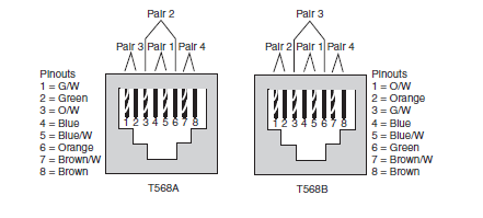
UTP Cabling pinouts for 10BASE-T and 100BASE-TX
Two
cooperating industry group, the Telecommunications Industry Association
(TIA) and the Electronics Industry Alliance (EIA), define standards for
UTP cabling, color coding for wires and standard pinouts on the cables.
.
.
EIA/TIA Standard Ethernet Cabling Pinouts
Note A UTP cable needs two pairs of wires for 10BASE-T and 100BASE-TX and four pairs of wires for 1000BASE-T.
To build a working Ethernet LAN, you must choose or build cables that use the correct wiring pinout on each end of the cable. 10BASE-T and 100BASE-TX Ethernet define that one pair should be used to send data in one direction, with the other pair used to send data in the other direction. In particular, Ethernet NICs should send data using the pair connected
to pins 1 and 2—in other words, pair 3 according to the T568A pinout
standard. Similarly, Ethernet NICs should expect to receive data using
the pair at pins 3 and 6—pair 2 according to the T568A standard. Knowing what the Ethernet NICs do, hubs and switches do the opposite—they receive on the pair at pins 1,2 (pair 3 per T568A), and they send on the pair at pins 3,6 (pair 2 per T568A).
| Local Cable End | Remote Cable End |
| 1 | 1 |
| 2 | 2 |
| 3 | 3 |
| 6 | 6 |
The
network shown uses a straight-through cable. A straight-through cable
is used when the devices on the ends of the cable use opposite pins when
they transmit data. However, when connecting two devices that both use
the same pins to transmit, the pinouts of the cable must be set up to
swap the wire pair. A cable that swaps the wire pairs inside the cable
is called a crossover cable. For example, many LANs inside an Enterprise
network use multiple switches, with a UTP cable connecting the
switches.
Because both switches send on the pair at pins 3,6, and receive on the pair at pins 1,2, the cable must swap or cross the pairs. The next figure shows several conceptual views of a crossover cable
.
| Local Cable End | Remote Cable End |
| 1 | 3 |
| 2 | 6 |
| 3 | 1 |
| 6 | 2 |
| Devices that transmit on 1,2 and receive on 3,6 | Devices that transmit on 1,2 and receive on 3,6 |
| PC NICs | Hubs |
| Routers | Switches |
| Wireless Access Points (Ethernet Interfaces) | |
| Networked printers |
1000BASE-T Cabling
Gigabit
Ethernet does have a concept of straight-through and crossover cables,
with a minor difference in the crossover cables. The pinouts for a
straight-through cable are the same—pin 1 to pin 1, pin 2 to pin 2, and
so on. The crossover cable crosses the same two-wire pair as the
crossover cable for the other types of Ethernet—the pair at pins 1,2 and
3,6—as well as crossing the two other pairs (the pair at pins 4,5 with
the pair at pins 7,8).
If
you have some experience with installing LANs, you might be thinking
that you have used the wrong cable before (straight-through or
crossover), but the cable worked. Cisco switches have a feature called
auto-mdix that notices when the wrong cabling pinouts are used. This
feature readjusts the switch’s logic and makes the cable work.